
CONSTRUCTIONS
Design parameters
Seismic action
.jpeg)
Pre-dimensioning of structural elements
The design seismic action is quantified in accordance with the provisions of code P100-1/2013, chapter 2 and chapter 3, and is defined by means of the following parameters:
a) the reference average recurrence interval (IMR) of the seismic action for the design at the Ultimate Limit State equal to 225 years (probability of exceeding 20% in 50 years), established according to the provisions of chapter 2.1 of the code;
b) the horizontal acceleration of the ground for design, ag, equal to 0.3g for Bucharest according to the
provisions of chapter 3 of the code, where g is the gravitational acceleration approximately equal to 10 m/s2
c) the control periods (corner) TB, TC, TD of the response spectrum for the horizontal components of the seismic movement for Bucharest established according to the provisions of chapter 3 of the code: TC=1.60 s, TB=0.32 s and TD=2 .00 s.

The normalized elastic response spectrum of the absolute accelerations for the horizontal components of the ground motion (β)
The normalized elastic response spectrum shown in the figure corresponds to a fraction of the critical damping, ξ, equal to 0.05. This value is suitable for structures in reinforced concrete frames, not having to modify the spectral values to take into account different values of ξ. By multiplying the normalized values of the spectral accelerations with the horizontal ground acceleration for the design, ag=0.3g, the elastic response spectrum of the absolute accelerations for the horizontal components of the ground motion with a maximum value of 7.5 m/s2 is obtained.
Design value of seismic force
Since the analyzed structure meets the regularity requirements specified in P100-1/2013 (section 4.4.3), the method of equivalent static lateral forces can be applied in the seismic calculation. In this method the seismic action is represented by a set of statically applied horizontal forces. The resultant of these forces is the design value of the seismic force.
The design value of the seismic force is determined according to the provisions of ch. 3, 4 and 5 of P100-1/2013:
where
γI, is the importance-earthquake exposure factor of the building which is established according to the provisions of chapter 4 of P100-1/2013
q the behavior factor which, for the analyzed structure, is established according to the provisions of chapter 5 of P100-1/2013
λ correction factor that takes into account the contribution of the eigenmode fundamentally through the effective modal mass associated with it to the overall seismic response
G the total weight of the building above the theoretical elevation.
The weight of the building can be calculated, roughly, as the sum of the axial forces in all the columns on the ground floor (see the following table). For a more accurate calculation, it must be taken into account that not all marginal and central pillars have the same related areas, respectively the same related beam lengths.
Therefore, the values of the axial forces in the columns of a category will not be the same. In the structural calculation, the design value of the seismic force was determined based on the weight automatically calculated by the calculation program and the seismic coefficient calculated below.
The product it is identified in design practice by the name seismic coefficient. To determine the seismic coefficient, it is
necessary to establish the values of the factors that enter into the calculation relationship (7). In this design phase, the vibration periods of the building cannot be determined by exact calculation but can be estimated using the simplified relationships given in annex B of the P100-1/2013 code.
For the analyzed building, the vibration period in the fundamental mode can be estimated with the relation T1=0.1n, where n is the total number of levels located above the theoretical height of embedment. For the analyzed building, a period of vibration in the fundamental mode equal to 0.9 s in each main direction results.
This value is less than 1.6 s (TC) and greater than 0.32 s (TB). It follows that the value β(T)=2.50 can be used to determine the seismic coefficient for both directions (see the previous figure). After the more accurate values of the natural vibration periods are determined through overall structural calculation, the seismic coefficient is recalculated, if necessary.
The building belongs to class III importance-earthquake exposure, being part of the category of structures of ordinary importance, for which the factor γI,e is equal to 1.0 (Table 4.2 of P100-1/2013). The correction factor that takes into account the contribution of the fundamental mode through the effective modal mass associated with it is taken equal to 0.85 according to 4.5.3.2.2 of P100-1/2013.
The behavior factor q is chosen equal to the maximum allowed value of 6.75, according to the provisions of 5.2.2.2 of P100-1/2013:
The report introduces the influence of some of the factors to which the overstrength of the structure is due, especially the redundancy of the construction. For structures in frames with several levels and several openings, it is equal to 1.35 according to the provisions of P100-1/2013.
This results in a seismic coefficient of 9.4% (Table 2). The design value of the seismic force is:

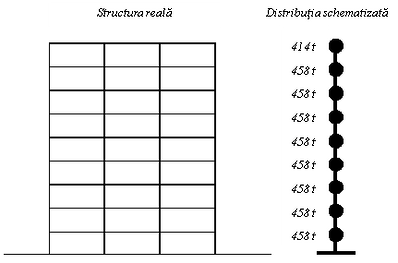
Schematic of the distribution of the
mass of the building by height
The design seismic force is the resultant of the horizontal seismic forces caused by the design seismic action. These seismic forces act on the building mass which is distributed. In practical design cases, the distributed mass of the construction is schematized by a finite number of masses located, as a rule, next to the floors.
At each level, the rigid and resistant floor for actions in its plane can ensure the in-phase oscillation of the related masses. The values of the masses at each level can be calculated based on the forces that load the pillars, by multiplying by the number of similar pillars and summing, separately, at each level.

Ciobanu Stefan Recipe - You Tube Chanel
After the schematization of the mass of the structure, the distribution of the design seismic force is necessary to perform the structural calculation. This can be done using relations (4.4) or (4.5) from P100-1/2013. If the masses of the structure at each level are close in value then relation (4.5) becomes:

where: Let be the seismic force at level i day the distance from the theoretical embedment level of the structure to the mass level with number i n the total number of levels above the theoretical embedment height. By applying this relationship, the seismic forces at each level, Fi, can be determined, as shown in Table 3. By accumulating these forces per height, ΣFbi , starting from the last level down, the level shear force diagram is obtained (see next figure). The base shear force represented by the sum of the level seismic forces is equal to the design seismic force.