CONSTRUCTIONS
Useful information
Structures in reinforced concrete frames
Pre-dimensioning of structural elements
In the case of statically indeterminate structures, the distribution of stresses caused by external actions in the structural elements depends on the stiffness of the elements. In order to determine the stresses and deformations through structural calculation, it is necessary to establish in advance the dimensions of the cross-sections of the structural elements. This design phase is called the pre-sizing phase. The dimensions of the sections established in the pre-dimensioning phase are checked and, possibly, modified following the structural calculation, in the dimensioning phase of the structure.
In the case of statically indeterminate structures, the distribution of stresses caused by external actions in the structural elements depends on the stiffness of the elements. In order to determine the stresses and deformations through structural calculation, it is necessary to establish in advance the dimensions of the cross-sections of the structural elements. This design phase is called the pre-sizing phase. The dimensions of the sections established in the pre-dimensioning phase are checked and, possibly, modified following the structural calculation, in the dimensioning phase of the structure.
Pre-dimensioning of beams
Beams are usually pre-dimensioned based on criteria that mainly aim to ensure the rigidity and bending ductility of the beams. Resistance to bending moment and shear force to be ensured by having longitudinal and transverse reinforcement. The most used pre-sizing criterion is the one that relates the height of the cross-section of the beams to their span (free opening):
In both directions, transverse and longitudinal, the beams have maximum spans of 6.00 m. The light of the beams is reduced, depending on the size of the cross section of the pillars. If it is considered that the posts will most likely have sections in the range of 70x70 cm ... 90x90 cm, the span of the beams can be between 5.10 m and 5.30 m.
Applying equation (4) results in hw values between 43 cm and 66 cm. Since the building has a medium height regime and is located in an area with high seismicity, it is likely that the seismic action will dimension the main structural elements.
As a result, to ensure the overall structural rigidity to horizontal actions, maximum values of the transverse height of the beams are chosen, as it results from the application of equation (4).
For practical execution reasons, hw is modulated to 5 cm, resulting in: hw=65 cm. The same reasoning can be done for the opening of 5.00 m resulting in hw=55 cm.

Figure 5: Beam geometry – notations
When determining the height of the beams, the architectural constraints must also be taken into account, especially regarding the free height, measured below the beams, to make openings for doors and windows or for the passage of suspended installations. If, for example, the architectural theme calls for a clear level height of 2.65m, then the height of the beams must be limited to 65cm. This limitation should be considered with the proviso that if further calculations show that the structure cannot meet the P100-1 code verification criteria for stiffness, overall strength and yielding mechanism, it should be renegotiated with the architectural designer.
Pre-dimensioning of pillars
In the case of columns, in the pre-sizing phase, the goal is to limit the normalized axial compressive stress in the columns to ensure their ductility. The ductility of long reinforced concrete elements is closely related to the level of axial stress.
To apply this pre-sizing criterion, it is necessary to determine the axial force in the columns in the seismic group. Three types of pillars are chosen for pre-sizing: corner pillar (intersection of axes A and 1), marginal pillar (intersection of axes C and 1) and central pillar (intersection of axes C and 2). In principle, for each type of column, the one that is likely to have the maximum axial force, usually caused by the larger related area, should be chosen. In the approximate calculation of the axial force in each column, the resulting loads distributed on the plate, on the perimeter beams, on the internal beams and the own weight of the columns are considered. These resultants are accumulated on the height, obtaining the axial force in the section on the ground floor.
The limiting condition of the axial force is placed only in the plastic zone of the column according to the optimal plasticity mechanism. In the case of the analyzed structure, the plastic joints must be formed at the base of the pillars on the ground floor.
For the marginal column the related floor area, Aaf, is 15.00 m2, the related beam length is 7.45 m and the related parapet length is 6.00 m (see figure).

Floor gravity load areas related to columns
Considering that at current level the distributed load on the slab is 7.45 kN/m2, the weight of the parapet is 4.10 kN/m, the weight of the beams (without slab) is 3.75 kN/m and the weight of the columns is 12.25 kN , results in a collected column load of 203 kN (112 kN from plate loads and 91 kN from the rest).

Ciobanu Stefan Recipe - You Tube Chanel
The width of the heart of the beams is taken to be equal to one-half to one-third of the height of the cross-section, modulating to 5 cm. However, the beams must be wide enough to allow the placement of the longitudinal reinforcements, preferably in a single row. A width of 25 cm practically only allows the placement of three bars in the current area and only two bars in the overlap joint areas.
Therefore, for the given structure, beams with a width of 30 cm are chosen. For practical reasons, the 30 cm wide and 65 cm high section is chosen for all beams, regardless of the opening. This section can be increased later, especially when the lateral displacement check is not met, and it is necessary to increase the rigidity of the structure.
Gravitational actions. Corner post
Areas and related lengths for each level
Aaf Laf parapet Laf grinzi Laf stalp
m2 m m m
.................................................................................................................
6.25 5.00 4.30 3.15
.................................................................................................................
uploads
..................................................................................................................
qplate parapet qbeam* qstalp
..................................................................................................................
kN/m2 kN/m kN/m kN/m
..................................................................................................................
Current level
7.45 4.10 3.75 12.25 The last level
6.69 2.40 3.75 12.25
By the same reasoning, a collected load at the terrace level of 181 kN can be determined. By accumulating these values per height, the axial force diagram is constructed. In a similar way, the axial forces in the corner post and the central post are determined. The values of the loads and the areas and lengths related to each type of load are given in the following tables.
Gravitational actions. Marginal pole.
Areas and related lengths for each level
Aaf Laf parapet Laf grinzi Laf stalp
m2 m m m
.................................................................................................................
15,00 6,00 7,45 3,15
.................................................................................................................
uploads
..................................................................................................................
qplate parapet qbeam* qstalp
..................................................................................................................
kN/m2 kN/m kN/m kN/m
..................................................................................................................
Current level
7.45 4.10 3.75 12.25 The last level
6.69 2.40 3.75 12.25
Gravitational actions. Central pillar
Areas and related lengths for each level
Aaf Laf parapet Laf grinzi Laf stalp
m2 m m m
.................................................................................................................
36.00 0.00 10.60 3.15
.................................................................................................................
uploads
..................................................................................................................
qplate parapet qbeam* qstalp
..................................................................................................................
kN/m2 kN/m kN/m kN/m
..................................................................................................................
Current level
7.45 4.10 3.75 12.25 The last level
6.69 2.40 3.75 12.25
The axial force diagrams, represented based on the values in the tables, are:
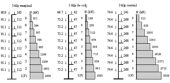
Column sections on the ground floor are determined from the condition that the average compressive axial stress, normalized by dividing by fcd, is less than 0.25, 0.30 and 0.35 for the corner, marginal and central column, respectively . In the end, after the application of the lateral loads, combined with the gravitational loads, the average normalized axial effort should be below 0.45 in all columns (P100-1, section 5.3.4.2.2.(1)). In practice, it is possible to go to higher values, up to 0.55, if the increase in ductility obtained by a strong transverse reinforcement in the plastic zone is quantified by calculation and the explicit ductility check is made. It is emphasized, however, that the ductility of the columns of frame structures depends decisively on the level of axial load, as high axial forces can lead to brittle breaks.
If the axial force in the marginal column, on the ground floor, is 1804 kN and the design value of the concrete compressive strength is 16.67 N/mm2, the required column area is 0.36 m2. For a post with a square section, the required length of the side of the cross section, modulated to 50 mm, is 600 mm or 650 mm.